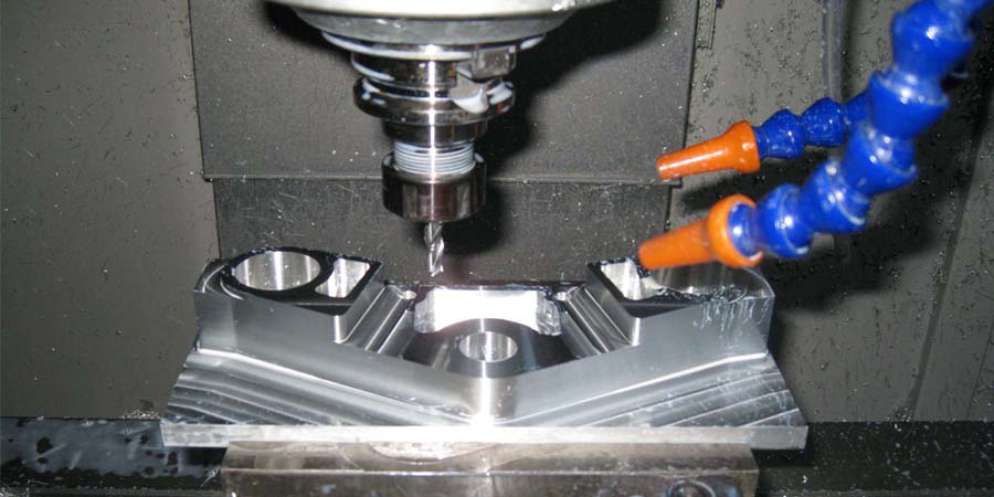
In the actual processing of the workpiece, we should also choose the correct operation method reasonably according to the specific workpiece processing accuracy and process requirements and specific processing conditions to ensure the accuracy of the product.
The accuracy of the machining center affects the quality of machining. Today we will consider the following aspects: machine selection, tool holder selection, tool selection, machining plan, program generation, operator requirements, etc., to ensure that CNC parts are processed When the machining accuracy has no problem.

1. The size of the workpiece is accurate, and the surface finish is poor
Cause Of Issue:
The tool tip is damaged and not sharp
The machine tool resonates and the placement is not stable
The machine has crawling phenomenon
The processing technology is not good.
Solution:
If the tool is not sharp after being worn or damaged, re-sharpening or selecting a better tool to re-calibrate the tool; the machine tool resonates or is not placed smoothly, adjust the level, lay the foundation, and fix it smoothly. The reason for the crawling of the machine is that the carriage guide rail is worn out, the lead screw ball is worn or loose, the machine tool should be maintained, and the wire should be cleaned after get off work, and lubricating oil should be added in time to reduce friction; choose a coolant suitable for workpiece processing. If it can meet the processing requirements of other processes, try to choose a higher spindle speed.
2. The phenomenon of taper and small head on the workpiece
Cause Of Issue:
The placement level of the machine tool is not adjusted properly, one high and one low, resulting in uneven placement; when turning a long axis, the contribution material is harder, and the tool eats deeper, causing the tool to give up.
The tailstock thimble is not concentric with the spindle.
Solution:
Use a level gauge to adjust the level of the machine tool, lay a solid foundation, fix the machine tool to improve its toughness; choose a reasonable process and appropriate cutting feed to avoid the tool being forced to give it a tool.
Adjust the tailstock.
3. The size of the workpiece is different from the actual size by a few millimeters, or there is a big change in a certain axis
Cause Of Issue:
The fast positioning speed is too fast, and the drive and motor can’t react
After long-term friction loss, the mechanical carriage screw and bearing are too tight and jammed
The tool post is too loose after changing the tool, and the lock is not tight; the edited program is wrong, the head and tail do not respond or the tool compensation is ended without canceling
The electronic gear ratio or step angle of the system is set incorrectly.
Solution:
If the rapid positioning speed is too fast, adjust the GO speed appropriately, cutting acceleration and deceleration and time to make the drive and motor work normally at the rated operating frequency
After the machine tool wears out, the carriage or screw rod bearing is too tight and jammed, and it must be re-adjusted and repaired.
If the tool post is too loose after tool change, check whether the reversal time of the tool post is satisfied, check whether the worm gear inside the tool post is worn, whether the gap is too large, whether the installation is too loose, etc.
If it is caused by the program, you must modify the program, improve according to the requirements of the workpiece drawing, select a reasonable processing technology, and write the correct program according to the instructions of the manual.
If the size deviation is found to be too large, check whether the system parameters are set properly, especially whether the parameters such as electronic gear and step angle are damaged. This phenomenon can be measured by using a dial indicator.

4. The effect of machining arc is not ideal, and the size is not in place
Cause Of Issue:
The overlap of vibration frequency causes resonance
Processing technology; parameter settings are unreasonable, the feed speed is too high, and the arc processing is out of step
Loosening caused by large screw gap or out of step caused by too tight screw
The timing belt is worn out.
Solution:
Find out the resonant parts, change their frequency to avoid resonance; consider the processing technology of the workpiece material, and make a reasonable program
For stepper motors, the processing speed F cannot be set too large
Whether the machine tool is installed firmly and placed steadily, whether the carriage is too tight after being worn, the gap is increased or the tool holder is loose, etc.
Replace the timing belt.
5. There is a change in the processing of a certain process of the workpiece, and the dimensions of the other processes are accurate
Cause Of Issue:
Whether the parameters of the block program are reasonable, whether they are in the predetermined trajectory, and whether the programming format meets the requirements of the manual.
Solution:
If the thread is disordered and the pitch is wrong, it immediately associates with the peripheral configuration (encoder) of the thread and the objective factors of the function.
6. Each process of the workpiece has an increase or decrease phenomenon
Cause Of Issue:
Programming errors; unreasonable system parameter settings; improper configuration settings
Mechanical transmission components have regular and periodic changes and failures.
Solution:
Check whether the instructions used by the program are executed in accordance with the required trajectory specified in the manual. You can judge by hitting the dial indicator. Position the dial indicator at the start of the program and whether the carriage returns to the starting position after the end of the program. Repeat the execution even if you observe it. As a result, master its laws.
Check whether the system parameters are set reasonably or considered to be changed; whether the relevant machine tool configuration meets the requirements on the connection calculation coupling parameters, and whether the pulse equivalent is accurate.
Check whether the transmission part of the machine tool is damaged, whether the gear coupling is uniform, check whether there are periodic and regular failure phenomena, and if there is, check the key parts and eliminate them.

7. Unstable dimensional changes caused by the system
Cause Of Issue:
Unreasonable system parameter settings; unstable working voltage
The system is affected by external interference, causing the system to lose synchronization
Capacitor has been added, but the impedance between the system and the driver does not match, resulting in loss of useful signal
The signal transmission between the system and the drive is abnormal
The system is damaged or internal failure.
Solution:
Whether the speed, acceleration time is too large, whether the spindle speed and cutting speed are reasonable, whether the parameter modification of the operator causes the system performance to change.
Install voltage stabilizing equipment.
Ground wire and make sure it is connected reliably, add anti-interference absorption capacitor at the pulse output contact of the driver
Choose the appropriate capacitor model.
Check whether the signal connection line between the system and the drive is shielded, whether the connection is reliable, and check whether the system pulse signal is lost or increased.
Send it to the factory for repair or replacement of the motherboard.
8. What should I do if the displacement of the workpiece affects the accuracy?
Cause Of Issue:
Machining of the above-mentioned workpieces on a three-axis CNC machining center sometimes causes problems such as movement of the internal structure of the workpiece to be processed and out-of-tolerance of dimensional accuracy. The cause of such problems is often caused by poor positioning accuracy of the secondary clamping.
Solution:
1) Leverage Dial Indicator Method
The lever dial indicator method is to suck the lever dial indicator on the spindle of the CNC machining center, make the dial indicator close to the horizontal position, and then lower the dial indicator to the precision datum level to be calibrated, and pass the pulse hand of the CNC numerical control system The wheel moves the worktable, and at the same time rotates the main shaft by hand, so that the dial gauge is pressed to the precision reference surface and shows the maximum value, and the workpiece is adjusted. At the same time, the relative coordinate value of the relevant direction of the CNC machining center numerical control system is cleared.
2) Pad Method
The pad method requires the use of standard pads and other auxiliary tools to translate the precision datum surface of the workpiece. Put a standard spacer block between the tool setter and the workpiece, install a photoelectric edge finder on the spindle of the CNC machining center, rotate the spindle at low speed, the photoelectric edge finder directly touches the left and right spacer blocks, and the second difference is the error value. The workpiece can be adjusted according to this difference. However, due to the gap between the spacer and the workpiece, this method is not as accurate as using a lever indicator.
The above is about the solutions that have been dealt with the problem of machining accuracy when the cnc machining center is processing parts, I hope it will be helpful to you.


