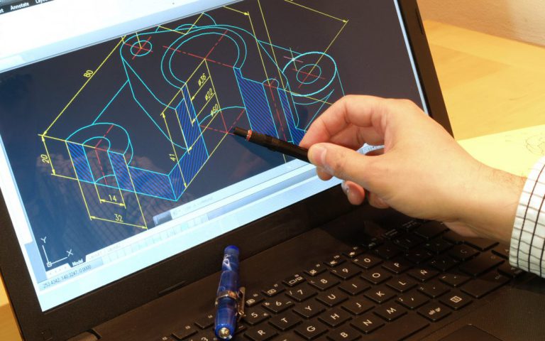
In contemporary manufacturing, Computer Numerical Control (CNC) machining technology has become crucial for enhancing production efficiency and precision. Computer-Aided Design (CAD) software plays an essential role in this process. This article will explore the application of CAD in CNC machining, optimizing production processes, and common file formats.
Use of CAD in CNC Machining
1. Synergy Between CAD and CNC Machining
CAD software enables designers to create precise 2D and 3D models, which can be converted into code that CNC machines can understand. This collaborative working mode not only improves design accuracy but also reduces the time from design to production.
2. Design Optimization and Simulation
Prior to CNC machining, CAD software can be used to optimize designs to ensure that part geometry and dimensions meet machining requirements. Designers can simulate within the software to predict potential issues during the machining process, such as material stress and heat distribution. This allows for adjustments to the design before actual machining, reducing material waste and machining errors.
3. Path Planning and Tool Selection
CAD software also aids in planning CNC machining paths. Precise path planning ensures tools move in the most efficient manner, reducing machining time and improving surface quality. Additionally, the software can select appropriate tools and cutting parameters based on design requirements, further enhancing machining efficiency.
4. Program Code Generation
Once a design is complete and validated through simulation, CAD software can generate G-code or M-code for CNC machines. These codes detail the tool’s movement path, speed, and depth, ensuring precise execution of the machining process. The generated code can be directly uploaded to CNC machines for automated production.
5. Quality Control and Feedback
During the CNC machining process, CAD software can also be used for quality control. By comparing actual machining results with CAD models, deviations and defects can be quickly identified. This feedback mechanism allows manufacturers to adjust machining parameters in a timely manner to ensure product quality.
6. Continuous Improvement
As technology advances, CAD software is also continuously updated, adding more intelligent features such as adaptive learning and AI-assisted design. These new features can help designers iterate their designs more quickly, improving the flexibility and responsiveness of CNC machining.

CAD File Formats
CAD software file types can be divided into two categories based on their usage scope and compatibility: universal formats and specific formats. Here is a description according to these two classifications:
Universal Formats
These file formats are supported by multiple CAD software and can be used for data exchange between different systems.
- DXF (Drawing Exchange Format):
Developed by AutoCAD, it is used to store 2D vector data and is widely used for data exchange.
- DWG (Drawing):
While primarily used by AutoCAD, many other CAD software can open or import DWG files.
- STEP (Standard for the Exchange of Product model data):
An international standard for exchanging complex 3D model data between different CAD systems.
- IGES (Initial Graphics Exchange Specification):
Another international standard format for exchanging design data between different CAD systems.
- STL (Stereolithography):
Commonly used for 3D printing, it stores surface geometric data of 3D models and is supported by various 3D modeling and printing software.
- PDF (Portable Document Format):
Although not a dedicated CAD file format, PDF can contain vector graphics and design data and is widely used for document sharing and printing.
Specific Formats
These file formats are usually closely associated with specific CAD software and are mainly used internally by that software.
- AutoCAD:
– DWG: The primary file format for AutoCAD, used to store 2D and 3D design data.
– DWF: Design Web Format, used for publishing and sharing design data online.
- SolidWorks:
– .SLDASM and .SLDPRG: Used to store assemblies and engineering drawings.
– .SLDPRT: Used to store part files.
- CATIA:
– .CGR: CATIA V4 file format.
– .CATPart and .CATProduct: Used to store part and product structures.
- Siemens NX:
– .prt and .asm: Used to store parts and assemblies, respectively.
- PTC Creo:
– .CREO and .ASM: Used to store Creo Parametric files.
- Rhinoceros 3D:
– .3DM: Rhino’s native file format.
- SketchUp:
– .SKP: SketchUp’s file format.
- Solid Edge:
– .PRT and .ASM: Used to store parts and assemblies, respectively.
- Inventor:
– .IAM and .IPT: Used to store assemblies and parts, respectively.
These specific format files often contain proprietary information and metadata related to their respective CAD software and may not be fully compatible with other software or require conversion. In practice, understanding the characteristics and compatibility of these file formats is crucial to ensure that design data can be smoothly exchanged between different software and platforms.
Looking for Custom CNC Machining Services?
SANS Machining offer a wide range of materials and provide services including CNC milling, CNC turning, EDM machining, grinding, and assembly. Our clients primarily come from industries such as custom automation, design, and robotics, and we serve customers in the USA, Ireland, and Japan.
We pride ourselves on our customer service, competitive pricing, and fast turnaround times. No order is too small, and you can always count on us to provide the highest-quality parts for your project.


