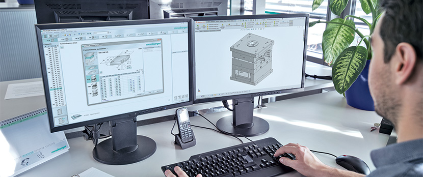
Mechanical drawings serve as the blueprint for manufacturing parts and assemblies, ensuring that every detail is captured accurately for production. These drawings must adhere to certain technical requirements to maintain consistency, precision, and clarity across various engineering and manufacturing processes. Here’s a summary of the common technical requirements for mechanical drawings:
1. Standardization and Compliance
Standards and Norms: Ensure all drawings comply with relevant industry standards such as ISO, ANSI, DIN, or JIS. These standards dictate the conventions for line types, dimensions, tolerances, symbols, and other drawing elements.
Title Blocks: Include a title block on each drawing, providing information such as the part name, drawing number, material specification, scale, and the names of the designer and reviewer.
2. Material Requirements:
The drawings usually indicate the type, specifications, and performance of the required materials. For example, parts may require the use of a specific metal or non-metal material to meet requirements for strength, wear resistance, or corrosion resistance.
3. Heat Treatment Requirements:
In order to improve the mechanical properties of the material, the drawings may specify heat treatment for the parts, such as quenching, tempering, annealing, etc. These processing procedures can alter the internal structure of materials, thereby improving their hardness, toughness, or corrosion resistance.
4. Surface Treatment Requirements:
In order to enhance the wear resistance, corrosion resistance, or aesthetics of the parts, the drawings may specify surface treatments such as galvanizing, chrome plating, spraying, etc.
5. Dimensions And Tolerances
Clear Dimensions: Provide clear and precise dimensions for all features, including lengths, diameters, radii, and angles. Avoid over-dimensioning or under-dimensioning.
Tolerances: Specify dimensional tolerances to define the allowable variation in part dimensions. Use general tolerances for less critical dimensions and specific tolerances for critical features.
Geometric Tolerancing: Apply geometric dimensioning and tolerancing (GD&T) to control the form, orientation, location, and runout of features. GD&T symbols ensure consistent interpretation of tolerances.

6. Views And Projections
Orthographic Views: Use orthographic projections (front, top, side views) to represent the part accurately. Include additional views (sectional, auxiliary, detail views) as needed to clarify complex features.
Isometric Views: Provide isometric or perspective views to give a three-dimensional representation of the part, aiding in better understanding and visualization.
7. Annotations And Callouts
Feature Callouts: Clearly annotate features such as holes, threads, surface finishes, and heat treatments. Use standardized symbols and abbreviations to convey information.
Material Specifications: Indicate the material to be used for the part, including specific grades and standards if necessary.
Surface Finish: Specify the required surface finish, typically using Ra values or other relevant parameters, to ensure the correct texture and quality of the machined surfaces.
8. Assembly Instructions
Assembly Drawings: For assemblies, provide exploded views and assembly sequences. Include part numbers, descriptions, and quantities in a bill of materials (BOM).
Fasteners and Joints: Detail the types of fasteners, welding, or other joining methods to be used, including torque specifications for bolts and screws.
9. Revision Control
Revision Blocks: Maintain a revision block on the drawing to track changes. Document the revision number, description of changes, and date of revision.
Change Management: Implement a robust change management process to ensure that all stakeholders are informed of and adhere to drawing revisions.
10. Legibility And Clarity
Line Types and Weights: Use different line types and weights to distinguish between various features (e.g., hidden lines, center lines, cutting planes). Ensure all lines are clearly visible and not overcrowded.
Text and Fonts: Use standard fonts and text sizes to maintain readability. Ensure all annotations and notes are legible and positioned clearly without overlapping with other drawing elements.
11. Scale And Units
Scaling: Ensure the drawing scale is appropriate for the part size and level of detail. Indicate the scale on the drawing.
Units: Clearly state the units of measurement (e.g., mm, inches) and ensure consistency throughout the drawing.
12. Other Special Requirements:
According to actual needs, the drawings may also include other specific technical requirements, such as dynamic balancing requirements for parts, sealing requirements, etc.
Conclusion
Adhering to these common technical requirements ensures that mechanical drawings effectively communicate the design intent, manufacturing details, and quality standards needed for production. Properly prepared drawings minimize misunderstandings, reduce errors, and improve the efficiency of the manufacturing process, ultimately leading to high-quality finished products.


