Chatter is a problem that every CNC machine operator must deal with from time to time. Machining vibration is a common problem in CNC manufacturing. Milling, turning or drilling will all cause parts to suffer this torture. It affects the quality and efficiency of processing, will cause the finish of the parts to decrease, and will damage and significantly shorten the life of the end mill. How to reduce the chatter in CNC machining is the main content we will discuss next.
 What is Machining Chatter?
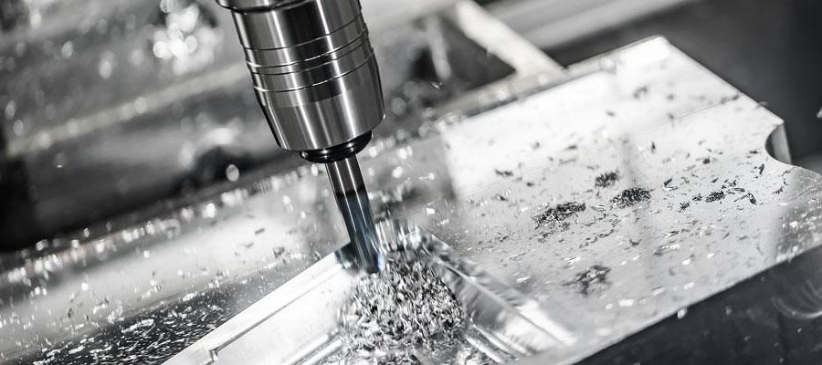
Machining vibration, also known as chatter, refers to the phenomenon of unwanted vibration generated during cutting operations in machining processes such as CNC milling, turning, and drilling, which produces fluctuations on the surface of the processed parts. This happens when the workpiece and the cutting tool vibrate at different frequencies, and it can be triggered by many process conditions: tool holders, cutting tools, part fixtures, and machine conditions.
These vibrations may be non-resonant, for example when using unevenly worn tools. Non-resonant vibrations are usually constant throughout the machining cycle and usually have mechanical causes that are easy to diagnose.
When you properly combine tools, workpiece clamping, machining strategies, and machine settings to produce vibrations that are equal to or close to the natural frequency of the machine, you will find vibrations caused by resonance. This type of chatter can only occur at certain points in the tool path, such as at concave corners.
Types of Chatter in Machining-Tool Chatter and Workpiece Chatter
There are two types of chatter to be aware of: tool chatter and workpiece chatter. With Tool Chatter, your machine and tools start to vibrate, which is then transmitted to the workpiece.
With workpiece chatter, the workpiece wall will vibrate. The latter usually only occurs when dealing with thin walls, but it can cause more or more problems than Tool Chatter. In this article, we will focus on “tool chatter”, but you can try to use these same techniques to reduce “workpiece chatter”.
Why Need to Reduce Chatter?
Chatter during machining can cause substandard surface finish and shorten tool life. Vibration marks will be visible on the processed surface, usually showing wavy patterns or regular marks. Constant tremor can cause uneven tool wear and even damage.
The vibration of CNC machine tools can usually be heard. An experienced mechanic will be able to recognize when chattering occurs through his unique voice.

Usually 100μm is used as the criterion for judging whether the tremor is appropriate. If the vibration amplitude of cutting exceeds 100μm, it may cause the tool or workpiece to loosen, and milling cannot be continued. When the vibration is less than 100μm, although machining can be carried out, there will be obvious vibration scratches on the surface of the part, which is not allowed on the surface of the finished product. Therefore, machining vibration should be limited within a reasonable range.
How to Reduce Chatter in CNC Machining?

1. Determine The Correct Tool Path
This is a very important step in cutting. According to the instructions, milling can be divided into downward milling and upward milling. If the direction of the milling force is consistent with the clamping direction of the workpiece, the vibration of the bent part can be eliminated. A CNC milling machine equipped with a ball or a ball screw, and a vertical machining center are very helpful in eliminating chatter vibration during CNC milling.
When using conventional tool paths on a CNC milling machine, the degree of engagement of the tools will vary. This can cause excessive force to be applied to the cutter at certain points in the tool path, which can cause chatter. Using a constant meshing tool path or reducing the depth of cut can help alleviate this situation.
2. Cut Properly
When a CNC milling machine uses a long and thin end mill to mill a deep cavity, it usually uses plunge milling, in which the milling cutter feeds axially like a drill. When milling deep cavities, the overhang of the long rod is usually more than 3 times the diameter of the tool rod. Only when the cutting vibration is not serious, the adjustment of cutting parameters may be effective. Conventional adjustment methods: reduce the speed of the tool or workpiece, reduce the depth of cut and increase the amount of cut per revolution. In addition, blades with large forward and backward angles are used with light chip breakers. The cutting wedge angle of the insert is the smallest in milling.

3. Choose The Right Cutter Tooling
Cutter tooling can greatly affect chatter. Considerations include the correct substrate, geometry, coating and aspect ratio. Programmers usually tend to use the largest tool that can be accommodated, but this may not be the ideal tool size. Long, thin tools are more likely to vibrate (and deflect) than short, fat tools. Therefore, choose the tool with the largest diameter. Minimize the number of tools protruding from the tool holder, and ensure that they are tightly fixed with firm runout accuracy. Combining multiple tools with variable groove shapes is an effective way to reduce vibration.
In addition, the use of sharp blades will reduce the cutting force of the CNC milling machine, and timely maintenance of the stability of the tool and the processing environment is a processing condition that cannot be ignored.
It is also important to continuously apply the correct tool pressure or chip load. On CNC milling machines, excessive chip flutes can cause chattering. Fewer chip flutes and variable pitch end mills can be used to help reduce resonant vibration caused by chip loads.
4. The Correct Tool Holder:
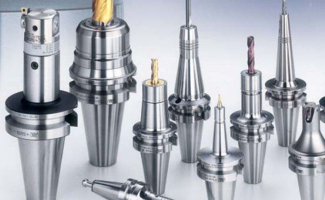
Ordinary tool holders (side lock, double-angle chuck and standard ER chuck) cannot provide the precision or stiffness required for high-performance machining. A better choice is a tool holder that combines end face and taper contact to provide high precision and high rigidity. This type of retainer engages with the precision ground surface of the spindle while in contact with the taper, which provides the required additional rigidity and also contributes to damping. The balance of all tools should be evaluated, and the surface quality can be improved even at lower RPM.
5. The Correct Workholding:
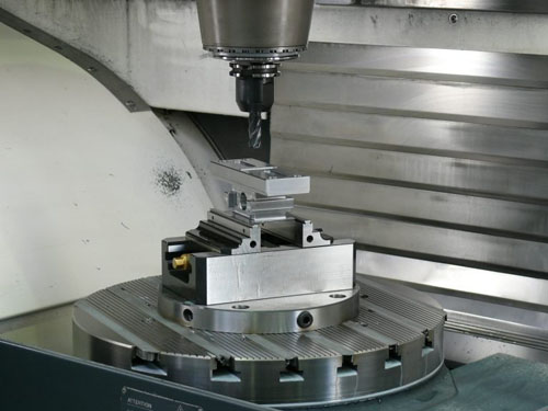
If the part is not properly secured, the part itself may vibrate and cause tremor. Check whether the chuck, vise, vacuum table or other workpiece holding device is applying sufficient pressure to the workpiece. Try to use a work fixture of the right size to apply clamping pressure to the part as evenly as possible.
Avoid clamping only one end of a long thin material. If this may be a problem, consider using a larger workpiece fixture or other fixture on the mill. Consider using a tailstock or a stable rest frame on the lathe.
When using thin-walled parts, the vibration of the shock-absorbing parts can be particularly challenging. One way to solve this type of chatter problem is to use filler materials to increase the stiffness of the part.
6. Machine Setting And Maintenance:
The CNC machine should be placed on a solid concrete floor without seams, cracks or any other discontinuities. Loose, soft, elastic or damaged floors will aggravate the jitter of CNC machines. Properly installed anchors or properly adjusted feet are also basic requirements for reducing jitter.
If you want to maintain good surface quality and tight tolerances on poorly maintained machines, you need to overcome mechanical problems other than those listed here. Keep the equipment regularly maintained to ensure optimal performance.


nice information