Consider the two cross-sections shown. Which cross section is a perfect circle? In fact, no cross section is perfectly round. How do we know if the cross section on the right is round enough? So we need to use circularity.

GD&T Circularity Definition
The geometric tolerance of circularity is one of the four shape controls, and the other types are straightness, flatness and cylindricity. Also known as circularity, it controls the circularity of features, such as the diameter of a cylindrical pin or hole. The goal is to set limits on the required accuracy of circular features related to perfect circles.
Some examples of circular features include cylinders, spheres, and cones. Sometimes round surfaces are used for moving parts, such as ball bearings or spools. In this case, the round shape helps to ensure that these parts move smoothly and wear evenly. Since circularity is applied to a single surface, this tolerance does not need to be datum-related.
Circularity GD&T Symbol

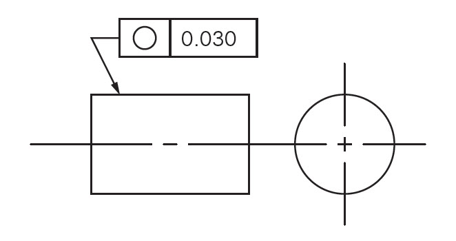
Drawing Callout:

Circularity Tolerance Zone
Two concentric circles, one inside and one outside, all points in the surface of the circle must fall into them. The tolerance zone lies on a plane perpendicular to the central axis of the circular feature. The tolerance zone consists of two concentric circles located on a plane perpendicular to the central axis of the part feature.
The difference between the radii of these two circles defines the allowable tolerance limit of the feature.
Circularity vs Other Callouts
The circle can sometimes be confused with other labels. Each label has a specific function and measurement method. The following information will help us understand the difference between different radial dimensions in geometric dimensioning and tolerances, and help us make more informed choices.
Circularity VS Cylindricity
Cylindricity is the 3D counterpart of circularity. The latter only cares about the circularity of the feature, the former also controls the straightness of the central axis of the circular feature.
Cylindricity tries to make the form of the feature as close as possible to a perfect cylinder.
Cylindricity is also different from circularity because it is suitable for features with a constant diameter and therefore not suitable for, for example, conical shapes.
Coaxiality annotation keeps the difference between the center axes of the multiple circular features of the part within the limits.
Circularity is a very common measurement method that can be used in all forms of manufacturing. Anything that requires a perfect round shape (such as a rotating shaft or a bearing) usually mentions circularity. You will often see this GD&T symbol on mechanical engineering drawings.
Circularity VS Coaxiality
Coaxiality annotation keeps the difference between the center axis of multiple circular features of a part within a limit.
Circularity is applied to a single feature, while coaxiality requires multiple features.
Another key difference is that circularity does not require a reference, while coaxiality cannot function without a reference axis.
Circularity And Concentricity
Concentricity is a special case of coaxiality, in which multiple features exist on the same plane.
When the plane perpendicular to the part axis contains the diameters of multiple features (for example, the inner and outer diameters of hollow tubes), the concentricity notation ensures that their centers are close enough to prevent swinging.
Circularity And Runout
The beating (or circular beating) combines circularity and concentricity to control the complete form of the feature. The tolerance zone for runout is similar to the circularity zone, so it is also a two-dimensional measurement.
Capture circularity and concentricity errors into a single measurement. It is the sum of circularity and concentricity errors.
If the parts are completely concentric, the runout measurement will give a circularity error. Similarly, when the part has perfect circularity, the beating represents the concentricity error.
Unlike circularity, runout also requires a reference axis.
Measuring Circularity
There are many ways to measure circularity. All of these methods require some skill and can be difficult to perform at the beginning. The method of measuring circularity is as follows:
- Use an altimeter
- Use coordinate measuring machine
- Use a micrometer
- Use an altimeter
- You can use the turntable and altimeter to measure the circularity.
Measurement Considerations
The circularity check of a sphere is difficult to measure because any cross-section through the center of the sphere is subject to tolerances. Therefore, unlike cylinders and cones, measurements on multiple planes are required to satisfactorily inspect parts.
Most machined parts are not oval and usually consist of multiple blades. When the part consists of an odd number of lobes, the circularity check may give wrong measurement results.
When we use a two-point measurement method (such as a micrometer) on a part with evenly distributed odd lobes, the result will show that the part is perfect, but it is not.
This error may result in the approval of parts that require further processing. This is the tricky part of circularity measurement, so a skilled inspector is required.
Points To Remember
The circularity tolerance zone is a radial tolerance zone, not a radial tolerance zone.
This control only works when applied to circular features.
In each cross-section, the label is applied independently of the other cross-sections.
In some cases, circularity measurement may give wrong measurement results.
No material condition modifier (LMC / MMC) is part of the feature control framework.
The circularity tolerance limit must be less than the tolerance limit of any other annotations that also control the circularity of the feature.
Related Post:
Quick Guide To GD&T Parallelism
Introduction to GD&T: Circular Runout
Introduction About GD&T – Flatness
Introduction About GD&T – Straightness


