The application of CNC machining is more and more widespread, and plastics are becoming more and more popular. They are light weight, easy to process, and generally cheaper than metal counterparts. At the same time, in the machinery manufacturing industry, in order to meet the requirements of flame retardancy, insulation and abrasion resistance, plastics are often used. So today we will talk about some tips for machined plastic parts, from part design to part processing and how to obtain a perfect finish on CNC processed plastic parts.
Tips In Plastic Part Design
Designing manufacturable plastic parts involves many important factors, which involve all areas of part design, tooling, material selection and production. First, the design intent or end use must be kept in mind, and parts must be built around functional requirements. Consider reducing weight, eliminating manufacturing and assembly steps, improving structural components, reducing costs and bringing products to market faster. In order to successfully achieve the design goals of plastic parts in the production process, the following important factors need to be considered.
1.Material Considerations
Manufacturers usually choose familiar plastic grades from similar applications, or rely on supplier recommendations. The resin selected in this way may be sufficient, but it is rarely the best. Plastic selection is a complex task, involving many considerations, such as: temperature, chemical resistance, heat resistance, flammability, and electrical and mechanical properties such as government and private standards, plastics and all assembly steps cooperation and other factors .
2. Radius
The radius should always take into account the thickness of the part-eliminating the possibility of high stress areas and possible fracture of the part. The general rule of thumb is that the thickness at the corners should be within the range of 0.9 times the nominal thickness of the part to 1.2 of the nominal thickness.
3. Wall Thickness
Designing parts to have the same wall thickness can help avoid many part defects that occur during the manufacturing process. When the plastic melts, it will flow to the area of resistance. If the thickness of your part is consistently inconsistent, the melt may flow into the thicker area first. When this happens, the thin area may not be filled properly. In addition, thicker areas tend to cool more slowly, and there is a risk of voids or sag defects. Designing parts with rounded corners will also help fill the parts correctly during the molding process.

4.Part Shrinkage
The shrinkage that occurs during the manufacturing of plastic parts may account for 20% of the volume. Crystalline and semi-crystalline materials are most prone to thermal shrinkage. It is known that the shrinkage of amorphous materials is small. Here are some easy ways to avoid molding shrinkage problems:
Adjust the formula and adjust the mold design according to the expected shrinkage rate to get the required size. Optimize processing parameters, such as molding temperature, melting temperature, injection speed/pressure/time, cooling time.
Tips to Plastic Machining
There are no plastic CNC machines. In fact, all machine tools used to cut plastics are metalworking tools. Their precise rigidity and power output enable them to easily process even hardened plastics.
1. Thermal effect
Since plastics have higher heat sensitivity than metals, most materials will become sticky due to heating when cutting tools are used for processing.
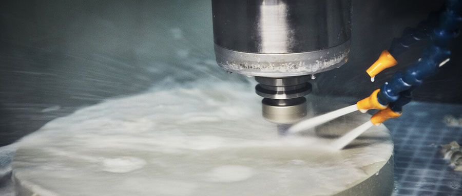
- When pour the coolant into the tool with a large flow, use the compressed air tube to blow the chips and the tool in the cutting area. This not only reduces the temperature of the cutting area, but also prevents plastic debris from sticking to the cutting tool.
- Increase the rake angle and the rear angle of the cutting tool, and maintain the sharpness of the cutting tool, reduce frictional heat, and prevent plastic deformation and heat generation.
- Properly increase the feed speed of the tool on the surface of the workpiece, select 200-300 m/min, and then select the feed rate 0.05-0.2 mm/rev.
- Combining the cutter head with cobalt-based chromium-tungsten cemented carbide and cemented carbide cemented carbide can improve productivity and processing performance.
2. The influence of force and deformation
The thermal expansion caused by the cutting heat of the part can cause the workpiece to warp and twist. The resilience exerted by the deformation of the workpiece on the tool and the fixture usually causes the tool to break and the fixture to rupture. In order to prevent these phenomena, the following measures have been taken:
- Please use a planer or small diameter milling cutter for stacking and reciprocating milling when processing the flat surface of thin plate parts that are easy to warp. When machining shapes, please use workpieces with multiple processing methods: place multiple workpieces in the middle, fix them up and down with a thin metal plate, and then process them at the same time. After the processing is completed, the workpiece is removed after it is completely cooled, the plastic material is hardened, the size of the workpiece is stable, and no warpage or deformation occurs.
- For thicker parts, in order to prevent the tool from breaking due to the resilience of the workpiece and the fixture from breaking when the shape is being processed, the intermittent cutting method is used to machine the outer contour through the up and down planing and the up and down grooving. Depending on the shape of the part, turning, boring, forming and grooving can replace milling and drilling. When milling and drilling are unavoidable, the diameter of the milling cutter should be as small as possible while ensuring the strength.
3. Cutting parameters
The main problem you need to pay attention to is excessive friction and plastic deformation of the part, not cutting. To avoid the second problem, always keep the cutter sharp and freeze it if the material used is not strong enough. Plastics become hard and brittle at low temperatures.
In order to prevent the chip from melting onto the CNC machined part, you need to keep the tool moving and prevent it from staying in one position for too long. Remove the chip as soon as possible. Therefore, the feed used for plastic processing must be large. When the feed speed is high, the spindle speed must also be fast. The approximate estimated speed is about 3 times the aluminum feed speed, and has a corresponding cutting speed.

Tips to Achieve Perfect Finish on Plastic Parts
A common problem in the CNC processing of thermoplastics is material extraction. This is the most common problem in dark plastics. How to solve this problem and achieve perfect finish on engineering plastic products? In order to prevent the plastic material from being pulled out, correct processing is the key. The following tips can ensure successful processing and achieve a smooth surface finish on the plastic.
1. Tool geometry
Make sure to use a cutting tool with the correct geometry so that the tool cuts the material correctly. Unlike CNC metal processing, engineering plastics require the shape of the tool to be positive or neutral. Too many positive numbers will cause the tool to dig in the material and produce a pull-out effect.
2. Correct fixing/clamping
Firmly fixing parts or fixing fixtures is another critical step for successful machining. Improper fixing may cause vibration between the CNC part and the tool, which may cause the tool to dig or go away when moving on the surface of the part. The correct fixation will ensure the correct contact between the workpiece surface and the tool to obtain the desired finish.
3. The correct feed speed and tool speed
The recommended feed rate and tool speed settings vary by material and material. Ensure that the cutting equipment is set to the appropriate processing rate, which can also extend the life of the tool without sacrificing production speed or efficiency.


