1. Wire Broken
(1) Poor discharge state—–lower the value of P. If the value of this value is greatly reduced and the wire is still broken, consider reducing the value of I until the wire is continuous. This operation will reduce the processing efficiency. If the wire breaks frequently, please refer to the following to find out the cause of the wire breakage.
(2) The flushing state is not good, such as the upper and lower nozzles cannot be veneered or open-ended processing. Usually the broken wire is in the processing area — lower the P value, and check whether the upper and lower nozzle caps are damaged, if damaged, please replace it.
(3) The conductive block is severely worn or too dirty. Usually, the location of the broken wire is near the conductive block—rotate or replace the conductive block and clean it.
(4) The guide wire part is too dirty, causing the wire to be scraped. Usually the broken wire is located near the guide wire part — clean the guide wire parts.
(5) The wire tension is too high—–lower the wire tension FW in the parameters, especially when cutting with a taper.
(6) The type of electrode wire and the quality of the workpiece material —–replace the electrode wire; reduce the P and I values until the wire is continuous.
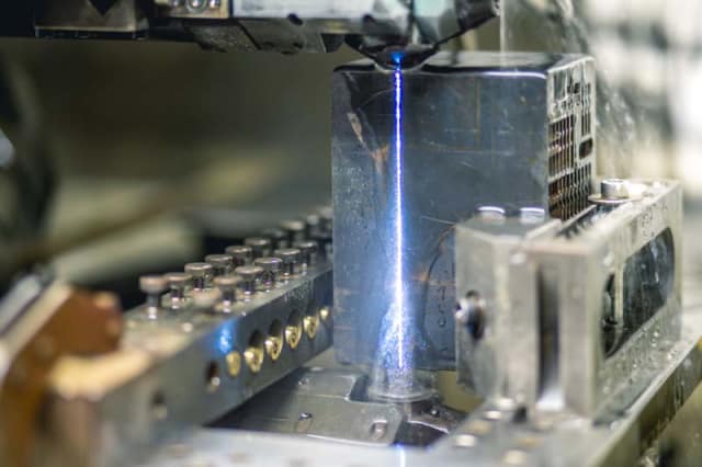
(7) The wire in the waste wire bucket overflows, causing a short circuit. Usually, the wire will be broken right after the processing is started-the waste wire in contact with the ground is returned to the waste wire bucket to eliminate the short circuit.
(8) When trimming the cut wire, the offset may be inappropriate, causing the trimming to be immovable and breaking the wire-reduce the margin between the offsets.
(9) Broken wire at the rear take-up wheel—check the wire pressure ratio of the take-up wheel, the standard value is 1:1.5.
(10) The cooling water of the conductive block is insufficient, usually the broken wire is located near the conductive block-check the cooling water circuit.
(11) The conductivity of deionized water is too high. Usually the broken wire is in the processing area. If it exceeds the standard value of 10μs, the deionized water is recycled to the standard value or less than the standard value before processing. If the standard value is still not reached , Please replace the resin.
(12) The quality of deionized water is poor. Usually the broken wire is in the processing area-the water in the water tank has turbidity or peculiar smell. Please replace the filter paper core and water.
(13) The wire is broken, there is waste wire embedded in the lower ceramic guide wheel of the lower arm or the operation is not flexible-clean and re-adjust and install the ceramic guide wheel, if necessary, check the wear of the guide wire nozzle and replace it.
(14) Excessive vibration of the tension wheel (unsteady wire transport) — Use a tension meter to correct the wire tension.
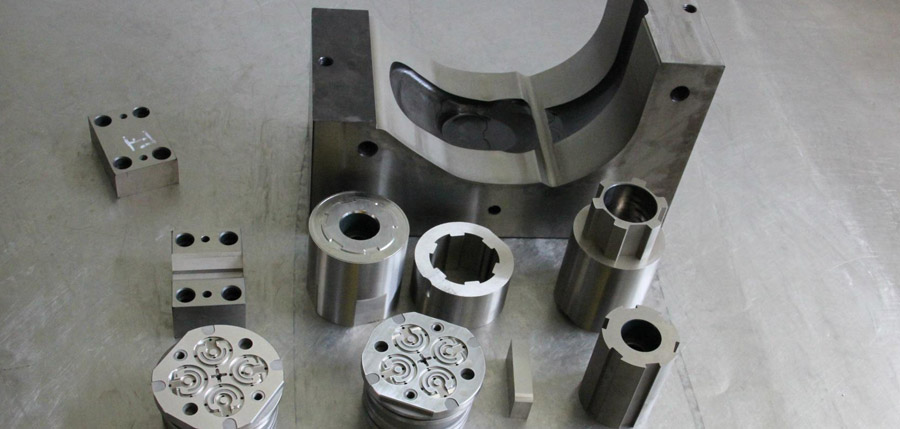
2. Processing Speed Problem
(1) Not according to the standard process, the upper and lower nozzles are more than 0.1mm away from the workpiece —– as far as possible veneer processing.
(2) The created TEC file is incorrect—–input the relevant process data correctly to obtain the correct TEC file.
(3) Modify the processing parameters, especially if the values of P and I are reduced too much, the processing speed will be greatly reduced. Reasonable modification is required.
(4) The flushing state is not good, and the standard flushing pressure is not up to the standard. If the veneer processing is indeed not possible, the processing speed must be correctly understood.
(5) Deformation of the workpiece leads to unstable discharge state during machining, especially trimming-control deformation.
(6) If ACO (Automatically Optimize Energy) is checked in the parameter, in some cases, the processing efficiency will be reduced a lot. In the case of stable cutting, the ACO function can be unchecked.
(7) For workpieces with many corners, high precision can be obtained by using high-precision parameters. The main cutting default str is 55, but it will reduce efficiency-reduce the value of corner strategy str (such as 33) or cancel (Set to 0) to increase the processing speed.
(8) The trimming speed is slow-the relative processing volume of each cut can be reduced a bit. If the trimming speed is increased, the offset of the main cutting can be reduced by 0.01 mm-0.02 mm.
(9) It is necessary to check whether the cooling water of the conductive block is normal, especially whether the cooling water of the lower conductive block is present.
(10) The main cutting efficiency is lower than before-please consider cleaning the lower guide wire core seat.
3. Surface Line Problems
(1) There is a problem with the quality of the electrode wire-it is recommended to replace it with a brand electrode wire.
(2) The problem of the type of workpiece material, or the workpiece contains impurities-replace the workpiece material.
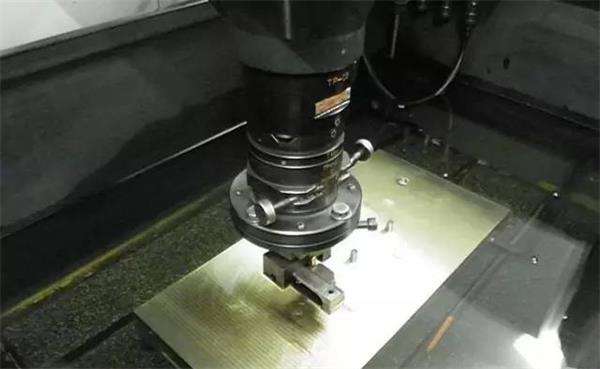
(3) The release of local internal stress in the internal organization of the workpiece will cause wire marks to occur in individual positions of the workpiece.
(4) The temperature of the working fluid is too high or the temperature change is too large-a refrigerator must be used to control the temperature of the fluid and ensure a suitable ambient temperature.
(5) The external environment of the machine tool is harsh and the vibration is large—improve the external environment.
(6) The conductive block is severely worn—–rotate or replace.
(7) Insufficient cooling water for upper and lower conductive blocks-cleaning related parts.
(8) The guide wire part is too dirty-cleaning.
(9) The working fluid is too dirty-clean the tank and working area, and replace the working fluid.
(10) Observe whether the discharge state is stable and whether there is a short-circuit back-off phenomenon during trimming—–If necessary, the UHP value can be increased by 1~2.
(11) If the fringe is darker-you can change the trimming parameter Smode to 10 and increase the UHP value by 2.
(12) If the discharge current and voltage are normal during trimming, but the speed is very low-the relative offset can be reduced.
(13) The flushing state is not good, and the standard flushing pressure and jet shape are not up to standard-check whether the upper and lower nozzles are damaged.
(14) Unsteady wire tension—–calibrate wire speed and tension if necessary.
4. The Surface Of The Workpiece Is Not Polished
(1) The relative offset is too small—–appropriately increase the relative offset.
(2) The deformation of the workpiece leads to uneven cutting speed during trimming-control the deformation.
(3) The quality of the electrode wire is poor-it is recommended to replace it with a brand electrode wire.
(4) The guide wire part is too dirty—–clean.
(5) The conductive block is severely worn—–rotate or replace.
(6) Wrong selection of process parameters—–select the correct TEC.
(7) The flushing state is not good, and the standard flushing pressure and jet shape cannot be reached —check whether the upper and lower nozzles are damaged.
(8) Unsteady wire transport—check and adjust.
5. Large Cutting Shape Error
(1) The hysteresis of the electrode wire when cutting corners will cause corners to collapse. For workpieces that require high corner accuracy, TEC parameters with corner strategies should be selected.
(2) In order to prevent deformation of large parts, the processing technology can be improved —–
- 1) Die: Make two main cuts, first increase the offset of the main cut by 0.1—0.2mm on one side, perform the first main cut to release the stress, and then use the standard offset for the second main cut cut.
- 2) Punch: Two or more temporary stays should be left, and it is processed by opening the shape during programming.
- 3) Appropriate starting position and supporting position; try to perforate as a threading hole.
(3) The wire alignment is not good—the wire alignment is performed again.
(4) The external environment of the machine tool is harsh and the vibration is large—improve the external environment.
(5) The type of electrode wire and the quality of the workpiece material are too poor—select the appropriate electrode wire and workpiece.
(6) The distance between the clamping position of the workpiece and the upper and lower nozzles is too large — adjust the clamping method.
(7) The wire speed or wire tension is abnormal — adjust or calibrate.
(8) The flushing conditions have changed significantly, causing the filament to vibrate greatly. The possible cause is that the upper and lower nozzles are damaged — please replace if damaged;
(9) Whether the axis and upper and lower arms of the machine tool collide, causing the mechanical accuracy of the machine tool to change.
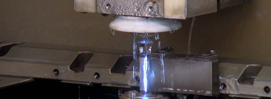
6. The Workpiece Is Concave Or Convex
(1) Optimize parameters—–In the case of concave, the Ssoll value of the main cutting and trimming process parameters can be reduced, the wire speed and tension can be increased, the last cut constant speed cutting speed can be increased, and the interval between trim 1 and the main cut can be increased The relative offset.
(2) The processing method when convex is opposite to that of concave.
7. Taper Error Of Straight Workpiece
(1) The quality of the electrode wire is poor-it is recommended to replace it with a brand electrode wire.
(2) Optimize the parameters—–Increase the wire speed and slightly increase the wire tension.
(3) Appropriate taper compensation is added to ISO program —–Use taper compensation function during programming.
(4) Adjust the upper and lower low pressure water flow rate—–correctly adjust the low pressure flushing liquid flow rate when trimming.
8. Traces Of The Feed Line
When machining concave molds, dents often appear at the cutting edge. For some precision molds, the precision and surface requirements are very high. The dents on the surface of the workpiece directly affect the surface quality of the product.
- It can be improved by adopting the method of arc in and arc out to advance and retract. When programming, enter the arc cut-in radius and exit radius,4-0.5 is OK.
- In the automatically generated program, the code for introducing the offset of cutting and exiting cutting is H000, and the default value is 0. Therefore, the entry and exit are at the same point, forming a secondary discharge, resulting in a dent of a few microns . It can avoid this phenomenon by adopting the oblique advance and oblique retreat to stagger the entry and exit points. You only need to assign the value of H000 in the program, generally 0.03-0.06.
9. Frequent Wire Breakage During Edge Finding
Please check if the wire is frequently broken when using 0.15mm or 0.1mm electrode wire to find the edge:
The wire tension in the machine configuration is incorrect—–The system defaults to set the edge-finding tension to 12. If you change to 0.15mm or 0.1mm electrode wire, you must reduce this tension value, otherwise it will be in the process of wire alignment. Wire breakage will occur.
The FW of 0.1mm wire electrode is adjusted to 3; the FW of 0.15mm wire electrode is adjusted to 7.
10. The Arc and Arc Connection Error Alarm
Because some mold drawing files are UG, Master CAM and other 3D software are converted to 2D drawings, some corners, arcs and actual dimensions of the converted 2D drawings are incorrect, and the accuracy of the programming software is connected. After the program is completed, the simulation processing is simulated. Sometimes it will alarm that the arc and the arc are connected incorrectly.
(1) Increase or decrease the arc I or J value in the alarm program line by 0.001.
(2) When using Fikus programming software, you can modify the subsequent processing configuration file from the original three decimal places to four decimal places. The specific steps are:
- 1) Find the Metalcam folder of the Fikus installation file, double-click to find the Fikusvisualcam folder.
- 2) Find the post folder, double-click to find the cfg folder.
- 3) Find the post-processing file edmAGIE-CA Frontier-G61.cfg.
- 4) Change 3 in item 5 to 4



I am maintenance engineer,I have problem with wire cut machine( Chinese Suzhou baoma 7740D) there is no power on electrodes when start work even I checked all parameters